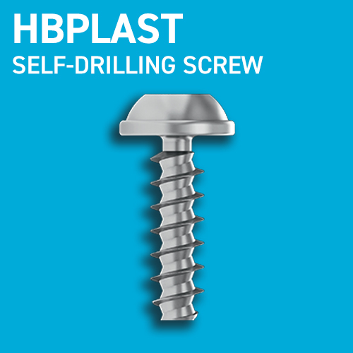
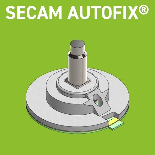
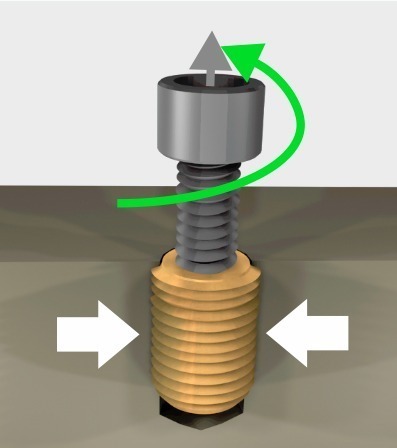
The tool positions the insert along its axis in the moulded well or drilling hole. self-drilling: the material is forced back without making chips self-tapping: the cutting slot cuts the material.
Phase 02
The locknut or the tool mechanism separates the tool and the insert. The material compresses the insert, holding it securely.
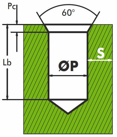
Lb Well depth: To recover the chips produced during installation Insert length +2 à 3 mm
Open Well
The insert must be fully buried in the material: Insert length +1 mm
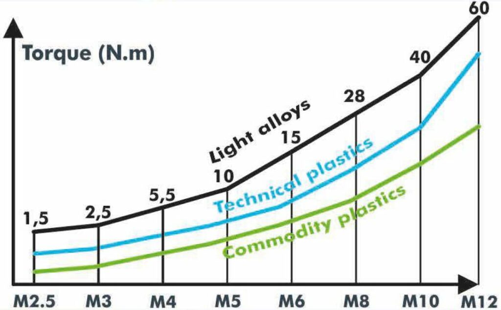
Commodily plastics
60° chamber Pc = 1 to 1.5 x ext. thread pitch
Technical plastics
& High-performances plastics
& Light allows
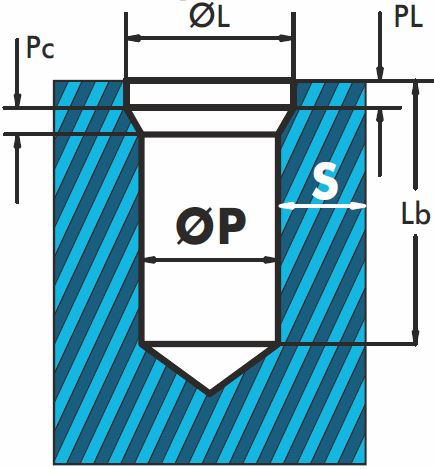
ØL =Ø ext + 0.2 to 0.4 mm PL =1 à 1.5 x ext. thread pitch Pc =1 à 1.5 x ext. thread pitch
Torque & speed for tempered steel type 2 screw insert
ØP / Well diameter
A larger hole will make it easier to fit the insert but at the expense of the holding force and torque resistance. Plan a counterbore and/or a chamber to fit the insert more easily an ensure that it is flush with the surface of the material.
S / Wall sickness
Depends on the material elasticity and the stress on the assembly
Commodity plastics: S ≥ 0.25 to 0.9 insert outer Ø
Technical & high performance plastics & light alloys: S ≥ 0.2 to 0.6 insert outer Ø
Internal thread
M2.5 M3
M4 M5
M6 M8
M10 M12
M14 M16
Speed of rotation in r.p.m.
from 800 to 1300
from 600 to 900
from 400 to 700
from 300 to 450
from 240 to 350
Tests strongly recommended: our laboratory is at your disposal
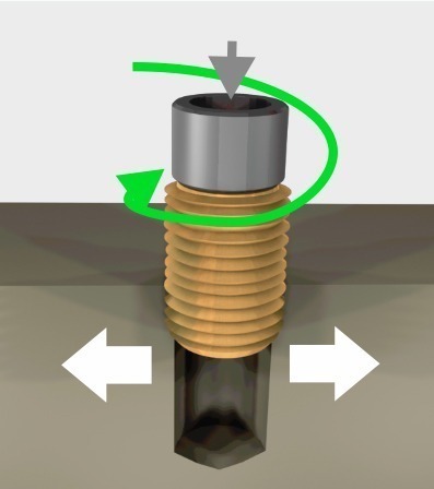
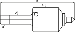
Fit a left-hand turn on the driving part of the tool. Mount the insert onto the tool with the slot or cutting holes facing down.
02
Engage the insert with light pressure at the start of installation to correctly form the first threads.
03
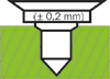
At the end of assembly, the insert must penetrate 0.1 to 0.2 mm ± 1/4 turn) below the surface of the part.
04
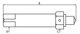
Using a wrench, lock the lock nut and unscrew the turn to the left to separate the insert from the tool. The stud of the tool is placed in the middle of the cutting slot so as not to block the clearance cutting chips.
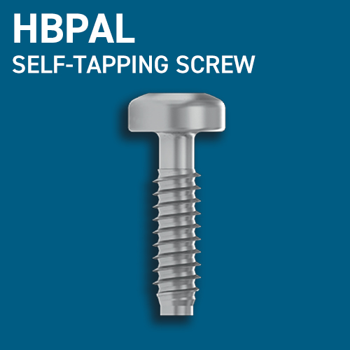
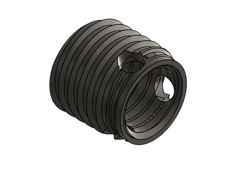
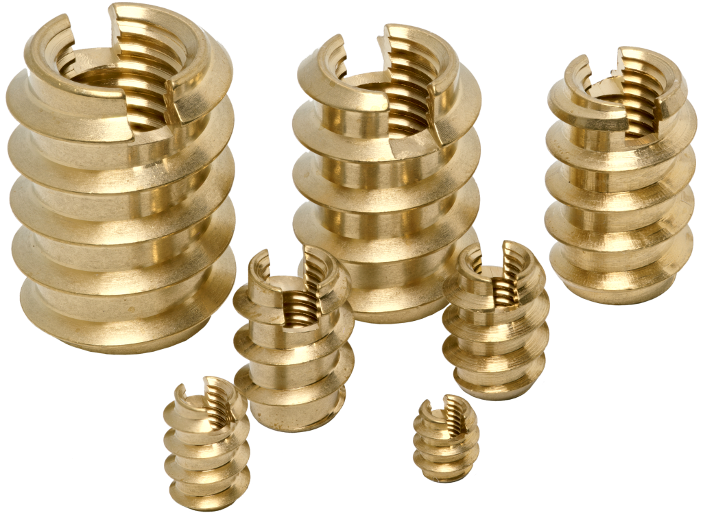
with cutting slot – external thread. 60°, with fine pitch
Internal thread
M3 (1/10 of mm)
Total length 6 mm
(1/10 of mm)
Metric pitch
External diameter 5 mm
(1/10 of mm)
Brass CW 614N
None
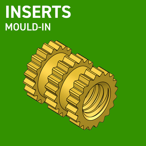
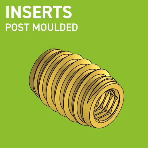
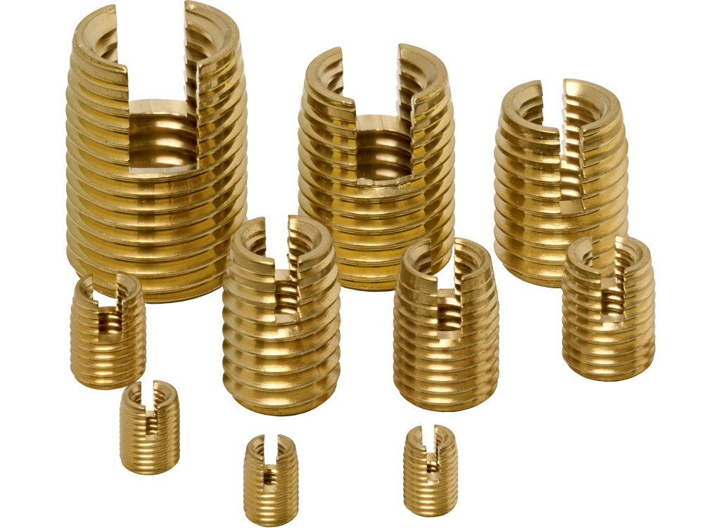
Sub Families S Mouled-in V Screw
E Expansion P Pressed-in U Ultrasonic
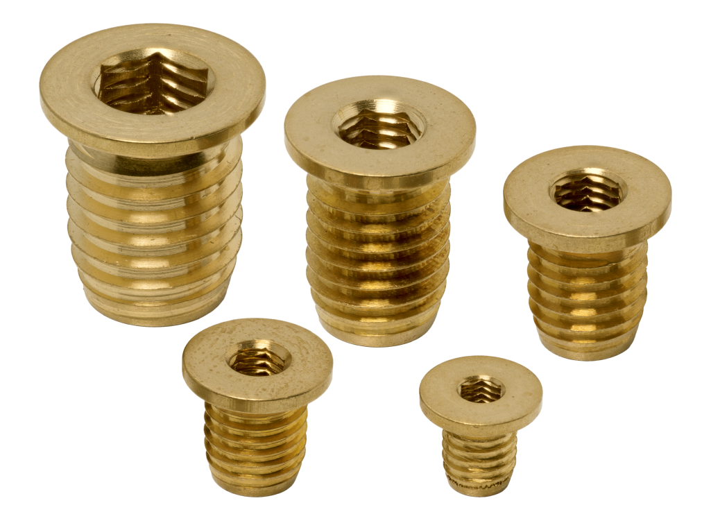
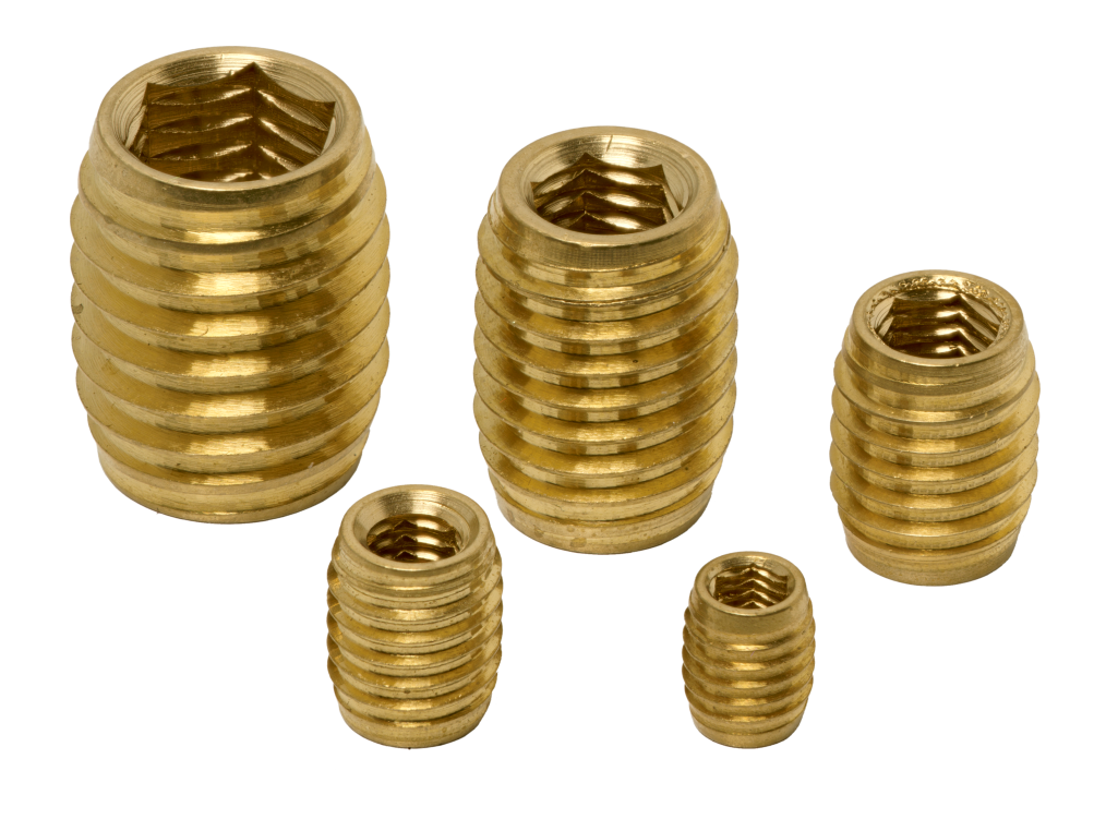
Screw insert Type K with head and thread 45° to bottom 160° – reversible + internal hexagon H without head and 45° thread at 160° bottom – reversible + internal hexagon 1 non-split – 60° ext. thread, ISO metric pitch 2 with cutting slot – 60° ext. thread, fine pitch 7 flat-bottom thread, 3 cutting holes 9 with cutting slot for soft platics and wood
Pour offrir les meilleures expériences, nous utilisons des technologies telles que les cookies pour stocker et/ou accéder aux informations des appareils. Le fait de consentir à ces technologies nous permettra de traiter des données telles que le comportement de navigation ou les ID uniques sur ce site. Le fait de ne pas consentir ou de retirer son consentement peut avoir un effet négatif sur certaines caractéristiques et fonctions.
Fonctionnel
Always active
Le stockage ou l’accès technique est strictement nécessaire dans la finalité d’intérêt légitime de permettre l’utilisation d’un service spécifique explicitement demandé par l’abonné ou l’utilisateur, ou dans le seul but d’effectuer la transmission d’une communication sur un réseau de communications électroniques.
Préférences
Le stockage ou l’accès technique est nécessaire dans la finalité d’intérêt légitime de stocker des préférences qui ne sont pas demandées par l’abonné ou l’utilisateur.
Statistiques
Le stockage ou l’accès technique qui est utilisé exclusivement à des fins statistiques.Le stockage ou l’accès technique qui est utilisé exclusivement dans des finalités statistiques anonymes. En l’absence d’une assignation à comparaître, d’une conformité volontaire de la part de votre fournisseur d’accès à internet ou d’enregistrements supplémentaires provenant d’une tierce partie, les informations stockées ou extraites à cette seule fin ne peuvent généralement pas être utilisées pour vous identifier.
Marketing
Le stockage ou l’accès technique est nécessaire pour créer des profils d’utilisateurs afin d’envoyer des publicités, ou pour suivre l’utilisateur sur un site web ou sur plusieurs sites web ayant des finalités marketing similaires.