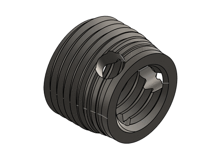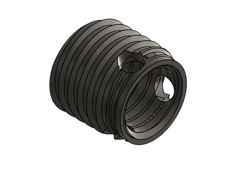

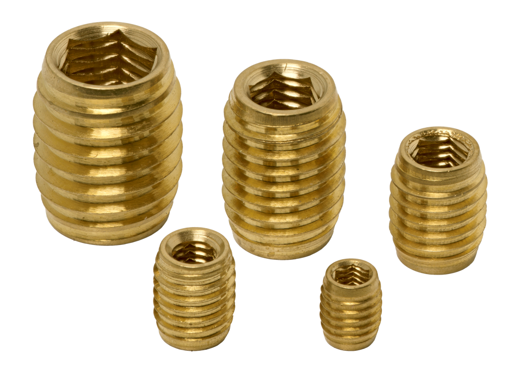
Reversible insert with hexagonal drive form (H) combined with internal thread. Innovative self-forming external thread for thermoplastics, thermosets and high density foams.
 ECO-CONCEPTION
100 % RECYCLABLE
Técnica de fijación – Grandes series – E-Shop
| Part Number | Thread M (6H) | Ø E x P | L (mm) | HEX (mm) | Well Ø*, soft and medium** | Well Ø*, hard*** | Recommended min. wall thickness (mm) | Technical sheet | 3D |
|---|---|---|---|---|---|---|---|---|---|
| IVH 030 060 F050 L 0 | M3 x 0.50 | 5 x 0.80 | 6 | 2.5 | 4.4 - 4.6 | 4.6 - 4.8 | 2.5 |  | |
| IV H 040 080 F065 L 0 | M4 X 0.70 | 6.5 X 1.00 | 8 | 3.2 | 5.9 - 6.1 | 6.1 - 6.3 | 3 | | |
| IV H 050 100 F080 L 0 | M5 X 0.80 | 8 x 1.25 | 10 | 4.2 | 7.2 - 7.4 | 7.4 - 7.7 | 3.5 | | |
| IV H 060 140 F100 L 0 | M6 X 1.00 | 10 X 1.50 | 14 | 5 | 8.8 - 9.1 | 9.1 - 9.4 | 4 | | |
| IV H 080 150 F120 L 0 | M8 X 1.25 | 12 x 1.80 | 15 | 7 | 10.8 - 11.2 | 11.1 - 11.4 | 5 | |
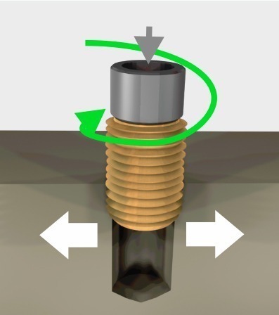
The tool positions the insert along its axis in the moulded well or drilling hole. self-drilling: the material is forced back without making chips self-tapping: the cutting slot cuts the material.
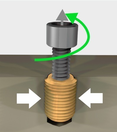
The locknut or the tool mechanism separates the tool and the insert. The material compresses the insert, holding it securely.
Lb Well depth:
To recover the chips produced during installation
Insert length +2 à 3 mm
The insert must be fully buried in the material:
Insert length +1 mm
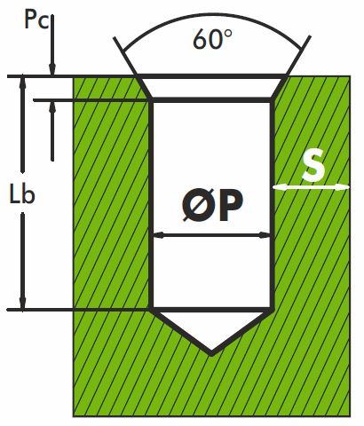
60° chamber
Pc = 1 to 1.5 x ext. thread pitch
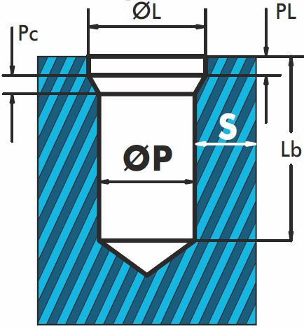
ØL =Ø ext + 0.2 to 0.4 mm
PL =1 à 1.5 x ext. thread pitch
Pc =1 à 1.5 x ext. thread pitch
A larger hole will make it easier to fit the insert but at the expense of the holding force and torque resistance.
Plan a counterbore and/or a chamber to fit the insert more easily an ensure that it is flush with the surface of the material.
Depends on the material elasticity and the stress on the assembly
Commodity plastics:
S ≥ 0.25 to 0.9 insert outer Ø
Technical & high performance plastics & light alloys:
S ≥ 0.2 to 0.6 insert outer Ø
| Internal thread | M2.5 M3 | M4 M5 | M6 M8 | M10 M12 | M14 M16 |
| Speed of rotation in r.p.m. | from 800 to 1300 | from 600 to 900 | from 400 to 700 | from 300 to 450 | from 240 to 350 |


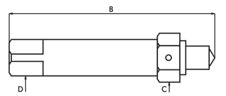
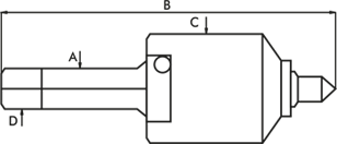
| Reference | Ø | B | D | C |
|---|---|---|---|---|
| 610 0 02500 | M2.5 | 55 | 5 | 7 |
| 610 0 03000 | M3 | 55 | 5 | 7 |
| 610 0 03500 | M3.5 | 60 | 5 | 7 |
| 610 0 04000 | M4 | 60 | 5 | 7 |
| 610 0 05000 | M5 | 75 | 8 | 13 |
| 610 0 06000 | M6 | 75 | 8 | 13 |
| 610 0 08000 | M8 | 75 | 8 | 13 |
| 610 0 10000 | M10 | 95 | 12.5 | 19 |
| 610 0 12000 | M12 | 95 | 12.5 | 19 |
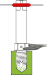
Fit a left-hand turn on the driving part of the tool. Mount the insert onto the tool with the slot or cutting holes facing down.

Engage the insert with light pressure at the start of installation to correctly form the first threads.

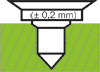
At the end of assembly, the insert must penetrate 0.1 to 0.2 mm ± 1/4 turn) below the surface of the part.
Using a wrench, lock the lock nut and unscrew the turn to the left to separate the insert from the tool. The stud of the tool is placed in the middle of the cutting slot so as not to block the clearance cutting chips.
| Reference | Ø | C | A | D | B |
|---|---|---|---|---|---|
| 610 0 02500 | M2.5 | 18 | 8 | 6.3 | 78 |
| 610 0 03000 | M3 | 18 | 8 | 6.3 | 78 |
| 610 0 03500 | M3.5 | 18 | 8 | 6.3 | 78 |
| 610 0 04000 | M4 | 18 | 8 | 6.3 | 78 |
| 610 0 05000 | M5 | 24 | 12.5 | 10 | 95 |
| 610 0 06000 | M6 | 24 | 12.5 | 10 | 95 |
| 610 0 08000 | M8 | 24 | 12.5 | 10 | 95 |
| 610 0 10000 | M10 | 32 | 16 | 12.5 | 118 |
| 610 0 12000 | M12 | 32 | 16 | 12.5 | 118 |
Adjust the depth stop so that the contact face of the tool penetrates 0.1 to 0.2 mm below the surface of the part.
Place the insert on the well.
Slot or sharp hole downwards.
Engage with light pressure.
Screw without pressure.

At the end of assembly, the insert must penetrate 0.1 to 0.2 mm ± 1/4 turn) below the surface of the part.

Product |
Sub-family |
Type |
Thread |
L |
Outer Shape |
Ø E |
Materials |
Specification |
|||||||
Exemple |
I |
V |
H |
0 |
3 |
0 |
0 |
6 |
0 |
M |
0 |
5 |
0 |
L |
0 |
|
Insert |
Screw |
without head and 45° thread at 160° bottom – reversible + internal hexagon |
Internal thread |
Total length 6 mm |
Metric pitch |
External diameter 5 mm |
Brass CW 614N |
None |
|||||||
| Sub Families S Mouled-in V Screw E Expansion P Pressed-in U Ultrasonic |
Screw insert Type K with head and thread 45° to bottom 160° – reversible + internal hexagon H without head and 45° thread at 160° bottom – reversible + internal hexagon 1 non-split – 60° ext. thread, ISO metric pitch 2 with cutting slot – 60° ext. thread, fine pitch 7 flat-bottom thread, 3 cutting holes 9 with cutting slot for soft platics and wood |
Materials |
Spécifications 0 None N Nickel plating ZnNi Zinc Nickel |

Applicable documents and agreements from the ARTEMA binding manufacturers’ union
Applicable documents and agreements from the ARTEMA binding manufacturers’ union